

Because of performed audit adopted at the company of cleanup process of gold concentrate (GC) from sluices of devices and GC processing on existing line of processing equipment, it is worth noting:
1 According to correct technology during the cleanup from sluices, maximum cleanup of GC should be cleaned from sluice until its next processing on relevant equipment. During performing of maximum cleanup of the head, it is allowed to clean only large splinter and clastic materials, materials from other sections should be dropped into placer carrier. During cleanups, the special tool is used – large rakes for initial cleanup of settled layer of GC, rabbles (wooden brushes), shovels, and spades with netlike surfaces.
2 According to the process of cleanup adopted at the company, head GC upgrade should be performed directly on sluice with the initial cleanup by legs without applying of any tools. Actually, the process represents not a cleanup of GC, but beating off placer concentrate, the major part of which is heavy earth materials (magnetic iron, pyrite, scheelite, chalcopyrite, hematite, limonite etc.) and goldilocks. During such process, light and plated gold is spreading over sluice and dropping into placer carrier, if such exists. In the case of absence of placer carrier, small gold becomes a loss.
3 Applied placer carrier with wedge valves instead of sliding ones is not designed for operation upload of GC. Placer finishing point is not equipped with inlet hutch for quick load of GC and its further automatic uniform serving into the processing equipment line. This essentially reduces performance of the site and requires personnel presence for manual adjustment.
 |
 |
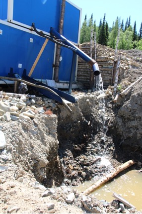
4 Location place of placer finishing point has chosen without consideration of necessary requirement of sufficient water supply for processing equipment. The point is located far from water. This leads to increasing of preparation time for operation of the point during filling the tank, requires additional pump station for pumping and supplying the water, and consequently additional costs for fuel and maintenance.
 |
 |
 |
 |
5 Technological circuit of processing equipment applied at the placer finishing point does not meet its application according to its specification and arrangement order.
5.1 Performance of applied equipment:
|
Name of equipment |
Screen |
Jigging machine |
Magnetic rougher |
Shaking table |
Concentrator |
|---|---|---|---|---|---|
|
Indication index |
GI1-0.6D (ГИ1-0.6Д) |
MOD-0.2SK (МОД-0.2СК) |
MMS-2PM (ММС-2ПМ) |
SKO-2 (СКО-2) |
KN-1.0 (КН-1.0) |
|
Units |
t/hour |
t/hour |
t/hour |
t/hour |
t/hour |
|
Performance |
2.0-5.0 |
0.5 |
1.0-2.0 |
0.3-1.0 |
1.0 |
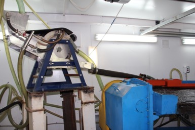
5.2 Magnetic rougher MMS-2PM (ММС-2ПМ) within the equipment circuit is installed actually after the jigging machine MOD-0,2SK (МОД-0.2СК) before the shaking table SKO-2 (СКО-2). However, it should be installed after screen and before the jigging machine for separation and preventing metal debris from entering the machine and block it, what may lead to failure. During the audit, there were discovered a fishhook, bearing rollers, and bolts in the bed of jigging machine.
| Magnetic rougher - Shaking table | Feeder - Jigging machine |
 |
 |
Also in the rougher, because concentration of magnetic iron in the earth material is extremely high, and concentration of color in whole is relatively low, as a result of flocculation (process of adhesion of small particles of dispersion systems into larger ones under the influence of adhesive force) a clutch occurs between particles of magnetic iron and color, what leads to their drop from the rougher to tails.
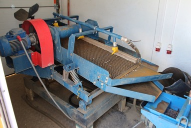
5.3 Heavy bed of jigging machine MOD-0,2SK (МОД-0.2СК) for its normal operation is not actually formed. As a bed material, inappropriate minerals are actually used, while pyrite or previously chopped lead should be used. Bed cells are filled unevenly; there are foreign bodies in the bed cells. Steps creating volume of liquefied material processed with pulsing flows of water are absent between the chambers. Grids of acceptable size are absent; there is only grid with 5-6 mm cell. Necessary grids of smaller sizes are absent. These sizes are 3.2 mm, 2.5 mm, 2.0 mm, 1.6 mm, designed for more effective increasing of concentration and reducing of underflow material rate.
 |
 |
Actually, heavy bed is absent. The normal process of operation of the jigging machine is also absent, when a layer of heavy minerals (heavy bed) rising and descending processes the incoming slurry capturing corresponding regarding density minerals from it and pushes them into underflow chamber of the same size as equipped grid on the screen, and first of all, minerals of higher density than they are, but more light ones pushed out by incoming material are pushed out and dropped into tails.
Now at the placer finishing site, MOD-0.2SK (МОД-0.2СК) is used at best as active screen without reaching effect of settlement of minerals according to their density, what leads to inappropriate gold recovery from processing liquefied mineral composition.
In addition, great amount of large dense material passed through to the processing line by the jigging machine interferes its further proper processing on the SKO (СКО).
5.4 Applied table SKO-2 (СКО-2) with diagonally located table top (table surface) riffle is designed for extraction of heavy minerals from GC slurry, but not its division into float of minerals of different density, where the most dense mineral, gold, should go to the collector separately from them. SKO-2 (СКО-2) is not able to extract refractory filmy, plated, and small gold from large volume of magnetic iron passing for drop-off. Due to the density and high load coefficient, as well as small size, magnetic iron does not allow settling gold on the surface of the table with area higher than particles fitting. In addition, colors got in layer of magnetic iron could not settle, because of high windage during serving; at the beginning of washaway, GC are washed into tails by portions.
SKO-2 (СКО-2) is not a sand table! It is used at huge processing facilities, mines, processing complexes. Therefore, there is no straight division of fractions by density on the SKO-2 (СКО-2); gold dust are not guaranteed extracted.
|
In fact. SKO-2 (СКО-2). Goldilocks, small fraction is not observed. |
Must be. SKO-1 (СКО-1). Goldilocks and the presence of fine gold dust of different density. |
 |
 |
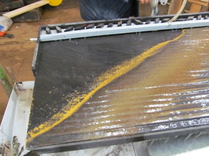 |
Visual difference by dust color: the difference in gold size is visual, |
During work on СКО-2 with diagonally located tabletop riffle, during the audit, drifting of small dusty gold along with magnetic iron into hutch section direction to material drop-off was observed.
IMPORTANT! According to the technology adopted by the company, GC is passed through on СКО-2 repeatedly, for 5-6 cycles, what multiply(!) increases the number of small gold losses, dropped with magnetic iron float!

Dung equipment operation, conventional systems of tubing of SKO-2 (СКО-2) table has been modified by company’s staff with the purpose of improvement of effectiveness of its performance. Observable positive effect after such modification has not been reached.
Furthermore, installed hand-made hydroelevator of processed GC load from intermediate pan for repeated processing supply excessive amount of water on the table, what also increases drifting of light gold to the drop-off.
Serving of GC on the table according to existing technology at the company is performed manually and unevenly. For maintenance of one existing table, minimum two employees are needed (manual supply, set-down of goldilocks, set-down of magnetic iron, cleaning of hutch section with magnetic iron).

5.5 From the very beginning of its operation at the placer finishing site, concentrator Itomak KN-1.0 (Итомак КН-1.0) had not provided its application. At the moment of audit, the concentrator had been decommissioned by personnel and excluded from technological circuit.
Centrifugal concentrator of any vendor, domestic or foreign, Itomak, Geoprom, Mezon (Итомак, Геопром, Мезон) etc., are all actually exact copy of each other.
They are not acceptable for operation at the PGCS, because they are not able to work for division of heavy placers under the large concentration of dense minerals.

During the operation with earth material with great concentration of high-density materials (magnetic iron in our case), concentrator riffles are immediately filled with magnetic iron.
Filling coefficient of magnetic iron is higher than of gold, especially of plated one; it is thickened by centrifugal force in concentrator so that newly settled tows of coherent mineral composition should be picked out with great effort and using tools.
The surface area of plated gold is higher so higher is windage; it could settle down in such heavy mineral so it easily drawn to the drop-off into tails by water flow.
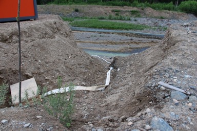
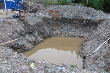
6 Drop-off of the processed black placer with probable concentration of small gold dust from magnetic rougher and from the table SKO-2 (СКО-2) is performed into hand-made control sluice with screen of handicraft production. The flow of dropped water slurry in uneven, jet, and chaotic; screens are not leaned to the mats and are not able to suppress and form a flow allowing settling of lost dropped small gold. The drop-off of placer from this sluice is performed into tail storage organized without measures for providing preserving of black placer and not efficiently equipped for its further extraction for new possible processing.
 |
 |
7 The drop-off of processed heavy black placer from the screen and jigging machine along with possible losses of small gold dust is performed directly into the same poorly organized tail storage.
 |
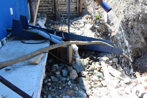 |
The tail storage is arranged without taking into consideration and realization of minimum requirements providing tail preserving, while there should be a special pit with volume of at least 1.5-fold of expected seasonal placer volume. The bottom of the storage should be covered with a layer of clay sand smoothing the pit’s ups and downs (boulderness, caving, and rocky bumps), protecting of processes GC from dilution (containing definite lossesи), preventing gold from sinking, and providing possibility of easy further extraction of placer until this layer and processing on the equipment of PGCS. Clay substrate is absent. Upper layer of storage bottom represents clay sand with huge boulder bed, which should be additionally eliminated before serving into PGCS.
8 Placer finishing site is not completed with equipment for processing and melting of placer gold for leading processing technology to logical finish – obtaining compact gold alloy as a commercial product, as well as details of minimum affination difference during settlements with affination factories.
9 On the Bazan site, the instruction of Product supplied regarding complex adjustment and regulation of all existing line of processing equipment of placer finishing site is absent, what interferes its correct operation.
CONCLUSION:
- Line of PGCS existing at the company is not fully arranged for entire cycle of small gold recovery, including one of black placer. Equipment applied is not agreed regarding application and does not comply with the class of equipment for refractory gold. The concentrator is not properly operative on corresponding grounds.
- Line equipment are not adjustable for providing effective operation and maximum recovery of small gold.
- Actually, uncontrolled and inestimable drop-off of small and plated gold exists in all units of processing line, because of incompliance of equipment application and inappropriate order of installation.
- Equipment requires greater number of personnel for providing its operation, as well as more time for processing of GC removed from devices.
- Tail storage is organized with violation of rules and does not provide quality collection of black placer for its probable repeated processing.
Taking into consideration all above mentioned, it might be said that the company does not have comprehensive qualitative placer gold-concentrating site.


